
Description
Key Technical Specifications
| Parameter | Specification |
|---|---|
| Manufacturer | Bently Nevada (Baker Hughes) |
| Module Type | 3500/33 16-Channel Relay Module |
| Front Panel P/N | 149986-01 |
| Rear I/O P/N | 149992-01 (standard); 149992-02 (failsafe variant) |
| Typical Order Code | 3500/33-01-00 |
| Relay Count | 16 independent SPDT outputs |
| Relay Type | Single-pole double-throw (SPDT), epoxy-sealed |
| Max Switching Voltage | 250 Vac |
| Max Switching Current | 5 A |
| Contact Life | 10,000 cycles (typical, load-dependent) |
| Logic Programming | AND/OR alarm-driven logic via 3500 Rack Config software |
| Power Consumption | ~5.8 W typical |
| Form Factor | Full-height module, slots to right of TDI/RIM |
| Hot-Swap | Supported (with redundant power) |
| Certification Note | Multi-cert (-02) variants have reduced voltage limits for hazardous-area compliance |
| TMR Note | TMR applications require 3500/34, not 3500/33 |
Product Introduction
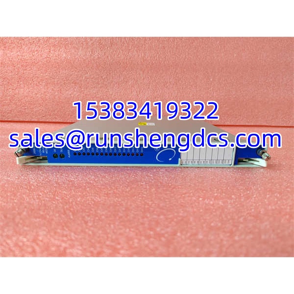
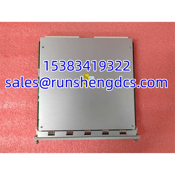
If the 3500/15 is the heart of the rack, the 3500/33 is the hand on the trip lever. The 149986-01 is the front panel assembly of the Bently Nevada 3500/33, a full-height 16-channel relay module that sits to the right of the 3500/22M TDI (or legacy 3500/20 RIM) in any standard 3500/05 rack. It does not measure anything itself — it reacts. Each of its 16 SPDT relays is driven by alarm logic that you define in the 3500 Rack Configuration software, using AND/OR combinations of alert/danger states, Not-OK conditions, or individual measured variables from any monitor channel in the frame.
That design intent matters. The 3500/33 is the module that turns a vibration exceedance into a real-world action: energizing a trip solenoid, closing a bypass valve, lighting a beacon, or sending a dry contact to the ETS. Because the logic is software-defined, a single 3500/33 can replace a nest of external interposing relays. The relays are epoxy-sealed and rated for 250 Vac / 5 A, with arc suppressors standard. The module draws about 5.8 W and is hot-swappable when redundant power is installed.
One important boundary: the 3500/33 is for conventional (non-TMR) relay logic. If your application requires triple-modular redundancy with 2oo3 voting at the relay level, you need the 3500/34 TMR relay module instead. Also note that the 149986-01 is only the front panel — it must be paired with the correct rear I/O module (149992-01 standard, 149992-02 failsafe) to function.
QA/QC Transparency SOP
- Intake & Pair Verification — Record front P/N 149986-01, rear P/N (149992-01 or -02), serial number, and certification suffix (-00, -01, -02). Reject units with bent rear connector pins, cracked relay housings, or mismatched front/rear P/Ns.
- Live Functional Testing — Install in a verified 3500/05 rack with a working 3500/22M TDI. Confirm the “OK” LED illuminates and the TX/RX LEDs flash during backplane communication. Download a test configuration that exercises at least four relay channels.
- Relay Contact Verification — Trigger each programmed relay via simulated alarm conditions. Measure contact continuity (NO/NC state) and verify clean switching. Check for contact welding, excessive bounce, or failure to release.
- Logic & Voting Validation — Verify that AND/OR alarm-driven logic executes as configured. Confirm that a Not-OK channel condition drives the expected relay state. Document the configuration file used for testing.
- Final QC & Packaging — Record relay channel test results, LED status, power draw (~5.8 W), and any anomalies. Pack with rear connector protected. Label clearly with both front and rear P/Ns — a 149986-01 without the correct rear I/O module is non-functional.
Field Engineer Gotchas
- Front/rear P/N pairing is mandatory. The 149986-01 front panel will not work without its matching rear I/O module (149992-01 or -02). Fix: Always procure or verify both halves. A 3500/32 rear I/O (125720-01) is physically different and incompatible.
- 3500/33 ≠ 3500/34. The 3500/33 provides conventional relay logic. It cannot perform TMR 2oo3 voting. Fix: If the rack uses TMR monitor channels and requires voted relay outputs, you need a 3500/34, not a 3500/33. Substituting one for the other changes the protection architecture.
- Certification suffix affects voltage rating. The -02 multi-cert variant has reduced maximum voltage to comply with ATEX/IECEx Zone 2 spacing requirements. Fix: Check the suffix on the nameplate before connecting 250 Vac loads. A -02 module on a high-voltage trip circuit may violate its certification.
- Relay contact life is load-dependent. The 10,000-cycle rating assumes typical conditions; inductive loads (solenoids, contactor coils) wear contacts faster. Fix: Use snubbers or flyback diodes on inductive loads. Log relay actuation counts if your configuration software supports it.
- Configuration must be re-downloaded after replacement. The 3500/33 does not store its own relay logic — it receives it from the rack configuration via the TDI. Fix: After installing a replacement, verify the configuration download completed and all relay LEDs reflect the expected state. A module with no downloaded config will power up but do nothing.
- Not-OK logic can be counterintuitive. A channel in Not-OK state (sensor fault, open circuit) can be configured to drive a relay — either to trip or to inhibit a trip. Fix: Review the alarm-driven logic for every relay before commissioning. An inverted Not-OK rule is a classic source of nuisance trips or, worse, failure to trip.
Bently Nevada 3500/33 149986-01
Application Scenarios
- Steam turbine ETS interface where the 3500/33 provides dry-contact trip signals to the emergency trip solenoid based on vibration, displacement, and overspeed alarms.
- Centrifugal compressor protection driving alarm beacons, seal-gas trip valves, and DCS interlocks from radial vibration and axial displacement monitors.
- Gearbox monitoring where relay outputs feed a PLC for sequential shutdown logic rather than direct hardwired tripping.
- Legacy 3500 rack expansion adding relay capacity when existing 3500/32 (4-channel) modules are fully utilized.
FAQ
Is 149986-01 the complete module?
No. 149986-01 is the front panel assembly. It requires the rear I/O module 149992-01 (standard) or 149992-02 (failsafe) to function.
How many relays does it provide?
16 independent SPDT relay outputs, each programmable via the 3500 Rack Configuration software.
Can I use it for TMR voting?
No. TMR relay applications require the 3500/34 TMR Relay Module. The 3500/33 supports only conventional AND/OR alarm-driven logic.
What is the maximum switching rating?
250 Vac / 5 A per relay contact (standard -00/-01 variants). The -02 multi-cert variant has a reduced voltage limit.
Does it store its own configuration?
No. Relay logic is downloaded from the 3500/22M TDI (or 3500/20 RIM) via the 3500 Rack Configuration software.
Is this module still available?
The 3500/33 remains part of the active 3500 product family. Specific suffix variants and rear I/O P/Ns should be confirmed with Baker Hughes or an authorized distributor.
Can I mix 3500/32 and 3500/33 in the same rack?
Yes. Both are relay modules and can coexist in available slots to the right of the TDI/RIM. Just ensure your configuration accounts for the different channel counts (4 vs. 16).