
Description
Product Introduction
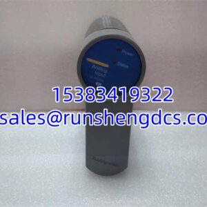
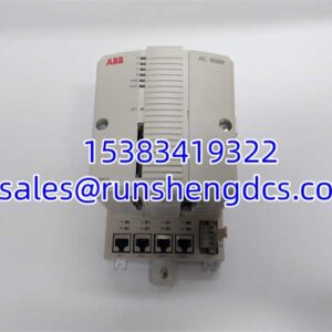
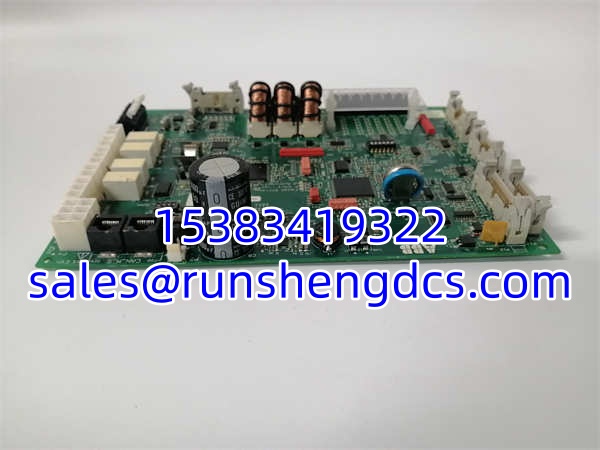
The ABB PQF4-3 TAS.580.0600G00 V01 is the critical translation layer between your analog field devices and the digital brain of your control system. Think of it as a high-fidelity sensor interpreter: it takes messy, real-world voltage signals and converts them into clean, precise digital data that your PLC or DCS can actually trust.
This module is engineered for demanding industrial environments, featuring a wide -10V to +10V input range and an impressive 0.1% precision. That level of accuracy matters when you’re controlling a chemical reactor or monitoring turbine vibration, where a 0.5% drift could mean the difference between optimal efficiency and a costly shutdown. It communicates via RS485, making it a flexible node in distributed I/O architectures. Whether you call it an analog input board or a signal converter, its job is the same: ensure the data feeding your control logic is rock-solid.
Key Technical Specifications
| Parameter | PQF4-3 TAS.580.0600G00 V01 Specification |
|---|---|
| Input Signal | Analog Voltage |
| Input Range | -10V to +10V |
| Output Signal | Digital (0-65535) |
| Precision | 0.1% |
| Communication | RS485 |
| Operating Temp | -40℃ to +85℃ |
| Dimensions | 120mm × 60mm × 30mm |
| Mounting | 35mm DIN Rail |
| Protection | Strong Anti-Interference (Shielding & Filtering) |
Compatibility & Replacement Matrix
| Your Current Model | Direct Replacement / Variant | Notes |
|---|---|---|
| PQF4-3 TAS.580.0600G00 V01 | PQF4-3 TAS.580.0600G00 V01 | Exact match. The “V01” is a critical version identifier. |
| TAS.580.0600G00 V01 | ✅ Same Hardware | Often listed without the “PQF4-3” prefix. Functionally identical. |
| TAS.580.0550G00 | ⚠️ Different Module | This is a Contactor, not an analog I/O module. Do not confuse. |
| TAS.580.0560G00 | ⚠️ Different Module | Also a Contactor. Completely different function. |
| AI620 | ❌ Different Platform | A separate ABB analog input module. Not a direct drop-in for this TAS series. |
Quality Inspection & SOP Transparency
Precision analog modules are sensitive. Here’s our validation process:
- Visual & Terminal Audit: We inspect the RS485 connector and analog input terminals for corrosion, bent pins, or signs of overheating. The “TAS.580.0600G00 V01” label is verified against known authentic markings.
- Power-On Self-Test: We apply power and verify the module initializes correctly without internal fault indicators.
- Signal Injection & Accuracy Test: Using a precision voltage source, we inject -10V, 0V, and +10V signals. We verify the digital output value matches the expected 0-65535 range within the 0.1% precision spec. Any deviation beyond tolerance = reject.
- RS485 Communication Check: We connect to a Modbus master and verify the module responds to register reads and configuration writes. No timeouts or CRC errors allowed.
- Final QC & Packaging: Anti-static bag, rigid foam protection, and a test report with the serial number and calibration data. If it fails the accuracy test, it’s scrapped. No field recalibration.
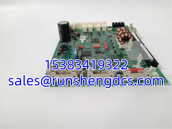
ABB PQF4-3 TAS.580.0600G00 V01
Common Replacement Pitfalls
- Ignoring the “V01” Suffix: The version suffix matters. A “V02” or unmarked board may have different firmware, input impedance, or calibration curves. Always match the full model number, including the version.
- Ground Loops: This is the #1 killer of analog signal integrity. If your new module reads erratically, check your grounding. The signal shield should be grounded only at the module end (single-point grounding). Grounding at both ends creates a loop that injects noise directly into your signal.
- RS485 Termination: If this module is at the end of a long RS485 bus, the 120Ω termination resistor must be installed. Missing termination causes signal reflections that look like intermittent data corruption.
- Input Overvoltage: The -10V to +10V range is absolute. A transient spike to +15V from a miswired sensor can destroy the input stage instantly. Always use transient suppression (TVS diodes or RC snubbers) on field wiring in noisy environments.
- Confusing with TAS.580.0550/0560: These are contactors, not I/O modules. They look similar in surplus listings but are electrically incompatible. Double-check the product description and application notes.
FAQ
A: No. Despite some misleading online listings, this is an Analog Input / Signal Conversion Module. It converts analog voltage (-10V to +10V) to digital data. It does not provide digital switching outputs.
Q: What does the “V01” in the model number mean?
A: It’s a hardware/firmware version identifier. Different versions may have different calibration constants, input filtering, or communication protocols. Always replace with the exact same version unless ABB explicitly states backward compatibility.
Q: My module reads 0 regardless of input voltage. What’s wrong?
A: 1. Check 24V/loop power to the module. 2. Verify the analog signal is actually reaching the input terminals (measure with a multimeter). 3. Check the communication; if the module isn’t polled, it won’t update values. 4. The input stage may be damaged from overvoltage.
Q: Can I use this module for current signals (4-20mA)?
A: Not directly. The specified input range is -10V to +10V. To use 4-20mA, you need an external precision shunt resistor (e.g., 250Ω for 1-5V) or a separate signal conditioner. Do not connect current sources directly to the voltage input.
Q: Is this module still supported by ABB?
A: The TAS.580 series is a mature platform. While new production may be limited, spare parts and technical support remain available through authorized distributors. For new system designs, consult ABB for current-generation analog I/O recommendations, but for maintenance of existing systems, this module is still a valid, supported component.