Description
Key Technical Specifications
- Product Type: Pulse Encoder Interface / Fiber Optic Comm Module
- Supported Drives: ABB ACS800 and ACS880 Series
- Communication Protocol: DDCS (Drive Drive Communication System)
- Feedback Type: Pulse Encoder Interface
- Signal Output: Active or Passive Current Output (4…20 mA typical)
- Explosion Protection: Zone 2 / Div. 2 (Active/Passive configurable); Zone 1 / Div. 1 (Fixed at order)
- Bus Compatibility: PROFIBUS PA address configuration required
- Installation: Standard drive slot mounting
- Hot-Swap Support: No (Requires drive power-down)
- Weight: ~0.5 kg (Typical for drive comm boards)
Product Introduction
When your ACS800 or ACS880 drive loses encoder feedback, the motor either trips on a fault or runs open-loop into a mechanical disaster. The ABB NTAC-02 is the OEM-native interface board that bridges the drive’s internal controller with external pulse encoders and fiber optic networks. It translates raw mechanical rotation into precise digital feedback, ensuring closed-loop vector control stays stable under heavy load.
This board handles DDCS communication and pulse encoder signals in a single slot. It supports configurable active/passive current outputs and integrates with PROFIBUS PA networks. Bottom line — if your drive is throwing encoder faults or fiber comm errors, and you’ve already ruled out the motor and cabling, this board is usually the culprit. Just verify your Zone 1/Zone 2 classification before ordering, because Zone 1 units have fixed configurations that can’t be reconfigured in the field.
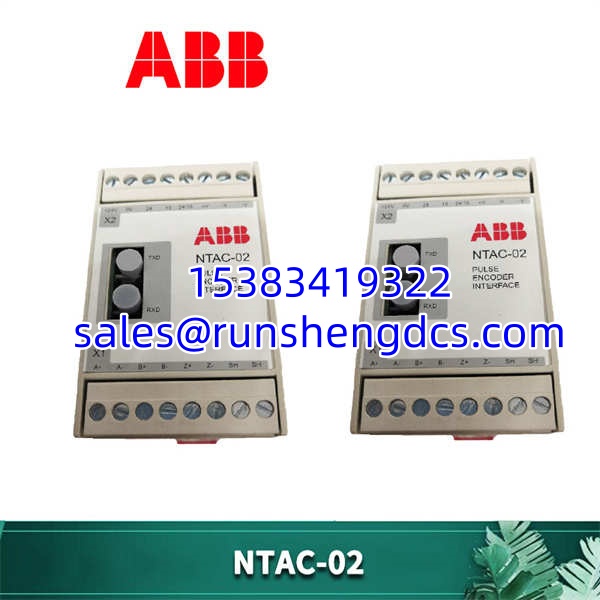
ABB-NTAC-02
QA/QC Transparency SOP
Encoder interface boards are sensitive to both electrical and physical damage. Here’s how we verify them:
- Intake & Origin Verification: We trace serial numbers and check for ABB authenticity markers. Counterfeit drive boards are common in surplus markets — we reject anything with rework solder joints or mismatched components.
- Live Functional Testing: Each NTAC-02 is installed in a test ACS800/ACS880 drive chassis. We verify DDCS link-up, inject simulated encoder pulses, and confirm the drive recognizes the feedback signal without faulting.
- Electrical Parameter Tests: Continuity checks on fiber optic transceiver pins. Voltage verification on encoder power supply rails. Insulation resistance test on current output terminals.
- Firmware/Config Verification: We read the board’s configuration dip-switch settings and verify active/passive mode matches the listing. For Zone 1 units, we confirm the fixed configuration matches OEM specs.
- Final QC & Anti-Static Packaging: Visual inspection of fiber optic ports and encoder connectors for damage. Ships in ESD-shielded packaging with test summary sheet.
Field Engineer Gotchas
- Zone 1 vs Zone 2 Configuration: Zone 2 units allow field-configurable active/passive current output. Zone 1 units are factory-fixed and CANNOT be reconfigured. I’ve seen guys buy a cheap Zone 1 board for a Zone 2 application, wire it up, and blow the output stage because the signal mode was wrong. Check your hazardous area classification before ordering.
- Encoder Wiring Polarity: Pulse encoder signals are differential. Swap A and A-bar and the drive will read position backwards or fault immediately. Triple-check your wiring against the NTAC-02 terminal diagram. Don’t trust the old wire labels — previous techs often mislabel these.
- Fiber Optic Connector Damage: The fiber ports on this board are fragile. Pushing a dirty or misaligned connector can crack the transceiver housing. Always clean fiber ends with approved wipes before mating. I’ve seen $3,000 boards killed by a single speck of dust in the connector.
- No Hot-Swap Support: This board does NOT support hot-swapping. You must power down the entire drive and wait for the DC bus capacitors to discharge (verify with a multimeter) before replacing. Backplane damage from live insertion is catastrophic and non-repairable.
- PROFIBUS PA Address Conflicts: If your NTAC-02 is on a PROFIBUS PA network, the bus address MUST be set before commissioning. Duplicate addresses will cause intermittent comm failures that are nearly impossible to diagnose. Set the address on the bench before installing.
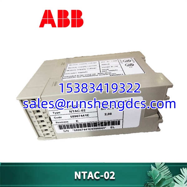
ABB-NTAC-02
Application Scenarios
- Paper Machine Drives: Providing precise speed feedback from shaft-mounted encoders to ACS800 drives in high-EMI environments, using fiber optic isolation to prevent ground loop noise from corrupting the feedback signal.
- Marine Propulsion Systems: Interfacing pulse encoders on diesel engine shafts with ACS880 marine drives, where Zone 1 hazardous area certification is mandatory and field-reconfigurable outputs are not permitted.
- Mining Conveyor Belt Control: Using DDCS fiber communication to link multiple ACS800 drives across long conveyor runs, with NTAC-02 boards providing encoder feedback for tension control and slip detection.
FAQ
Q: Can I configure active/passive mode in the field?
Only if it’s a Zone 2 / Div. 2 rated unit. Zone 1 / Div. 1 units have fixed configurations set at the factory and cannot be changed. Check the marking inside the terminal box or the order confirmation to determine which variant you have.
Q: Is this board hot-swappable?
No. You must fully power down the drive and verify DC bus voltage is below 50V before replacing. Live insertion will destroy the board and potentially damage the drive’s main control panel.
NTAC-01 is the older generation encoder interface board. is the direct replacement with updated firmware and improved EMI immunity. They are NOT pin-compatible — do not attempt to cross-substitute without verifying drive firmware compatibility.
Q: My drive shows “FIBER COMM FAULT” — is this board bad?
Maybe, but check the obvious first. Inspect the fiber cable for breaks, clean the connectors, and verify the fiber length doesn’t exceed spec (typically 2km for multi-mode). Swap the fiber cable first — cables fail far more often than boards. If the fault persists with a known-good cable, then suspect the .
It’s been discontinued by ABB, but it remains fully supported in current drive firmware and is widely available through surplus channels. For new builds, ABB recommends newer communication boards, but the remains a valid drop-in for existing /ACS880 installations.
Q: How do I verify the encoder feedback is correct after replacement?
Use the drive’s built-in oscilloscope function or DriveWindow software to monitor the encoder position and speed feedback in real-time. Jog the motor slowly and verify the position count increments correctly. Then run a closed-loop auto-tune to confirm the drive can lock onto the encoder signal under load.