
Description
Product Introduction
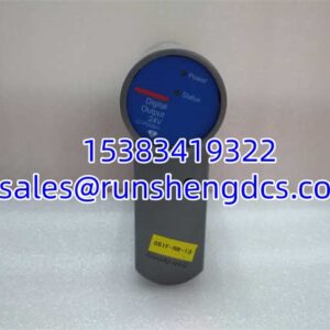
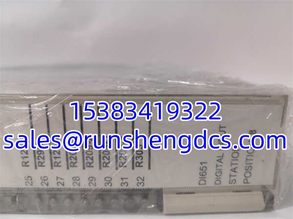
The ABB DSQC 651 is the most common “handshake” card you’ll find in an IRC5 robot cabinet. Think of it as the robot’s external nervous system. Without it, your robot is an isolated island; with it, you can wire up start buttons, safety interlocks, conveyor encoders, and gripper solenoids.
It’s a DeviceNet node, meaning it lives on the fieldbus, not directly on the main CPU board. You get 8 digital inputs (DI), 8 digital outputs (DO), and 2 analog outputs (AO). The analog outputs are a key differentiator here; many basic I/O boards skip them, but the DSQC 651 lets you send variable signals (like speed references or valve positions) without needing a separate analog card. The address is set via physical jumpers on the X5 port (typically 10-63), so if you’re swapping a dead unit, match the jumper settings exactly or the controller will throw a “DeviceNet Node Missing” fault.
Key Technical Specifications
| Parameter | DSQC 651 Specification |
|---|---|
| Digital Inputs | 8 Channels (24V DC, Sink/Source) |
| Digital Outputs | 8 Channels (24V DC, 0.5A max) |
| Analog Outputs | 2 Channels (0-10V or 4-20mA) |
| Bus Protocol | DeviceNet |
| Node Address | 10-63 (Set via X5 Jumpers) |
| Power Supply | 24V DC (Internal regulation) |
| Input Address Range | 0-7 (DI), 32-39 (DO) |
| AO Address Range | AO1: 0-15, AO2: 16-31 |
| Status LEDs | Module Status, Network Status, I/O Indicators |
| Connector | X1 (I/O), X3 (Power), X5 (DeviceNet) |
Compatibility & Replacement Matrix
| Your Current Model | Direct Replacement / Variant | Notes |
|---|---|---|
| DSQC 651 | DSQC 651 | Exact match. Verify the full part number (e.g., 3HAC022286-001). |
| D651 | ✅ Same Unit | Common field abbreviation for DSQC 651. |
| DSQC 652 | ⚠️ Different Config | Has 16 DI / 16 DO but NO analog outputs. Not a drop-in if you use AO. |
| DSQC 1030 | ✅ Modern Upgrade | Newer version with more I/O and diagnostic features. Check firmware compatibility. |
| DSQC 653 | ❌ Different Type | Analog I/O board. Completely different pinout. |
| PLC DI651 | ❌ Wrong Product | 3BHT300026R1 is a PLC module, not a robot I/O board. |
Quality Inspection & SOP Transparency
I/O boards are failure points due to field wiring. Here’s how we validate every DSQC 651:
- Visual & Jumper Check: We verify the “DSQC 651” label and inspect the X5 jumper block for corrosion or missing pins. The DeviceNet connector (X3) is checked for bent pins.
- Power-On Self-Test: We apply 24V DC and verify the “Module Status” LED turns green. A flashing red LED indicates internal firmware corruption.
- DeviceNet Handshake: We connect to a DeviceNet scanner and verify the node responds to polling at the configured address. No “Unconnected Request” timeouts allowed.
- I/O Loopback Test: We force each of the 8 DOs and verify the physical LED lights up. We inject 24V into each DI and verify the status bit changes.
- Analog Output Calibration: We command 0V, 5V, and 10V on AO1/AO2 and verify the output with a multimeter. Drift >1% = reject.
ABB DI651
Common Replacement Pitfalls
- Wrong Jumper Address: The X5 jumpers define the DeviceNet address. If the old board was set to 10 (jumper 8+10 removed) and you install a new board at default 63, the robot won’t see it. Always match the jumpers.
- Confusing 651 vs. 652: As mentioned, the 651 has analog outputs. If you swap a 651 for a 652, your analog signals will vanish, and the controller will fault. Check the label before installing.
- DeviceNet Termination: If this board is at the end of the DeviceNet cable, the termination resistor (usually a DIP switch or jumper on the X3 connector) must be ON. Missing termination = intermittent communication errors.
- 24V Power Wiring: The DSQC 651 requires 24V on the X3 connector. If you’re replacing a board that died, check the 24V supply first. A shorted field device often kills the I/O board’s internal fuse or regulator.
- Firmware Mismatch: While rare, older DSQC 651s may have firmware that doesn’t play nice with newer IRC5 controllers. If the new board won’t configure, try updating the robot controller’s system software or downgrading the I/O board firmware via RobotStudio.
FAQ
Q: What does the “D651” abbreviation mean?
A: It’s just shorthand for DSQC 651. You’ll see it in robot programs, electrical schematics, and maintenance logs. They refer to the exact same hardware.
Q: How do I set the DeviceNet address on the DSQC 651?
A: Use the jumpers on the X5 port. The address is binary-coded. For example, to set address 10, remove jumpers on pins 8 and 10 (since 8+2=10? Correction: It’s binary weighting. Pin 6=1, 7=2, 8=4, 9=8, 10=16, 11=32. To get 10, you need 8+2, so remove pins 7 and 9. Always consult the manual for the specific binary map.)
Q: My DSQC 651 shows “DeviceNet Node Fault”. What do I do?
A: 1. Check the 24V power LED. 2. Verify the DeviceNet cable is seated and terminated correctly. 3. Confirm the jumper address matches the RobotStudio configuration. 4. Check for shorts on the field wiring (a shorted sensor can drag down the bus).
Q: Can I use a DSQC 652 instead of a DSQC 651?
A: Only if you do not use the Analog Outputs. The 652 has more digital I/O but lacks AO. If your program references AO1 or AO2, the 652 will cause a configuration error.
Q: Is the DSQC 651 compatible with OmniCore controllers?
A: No. OmniCore uses the DSQC 1030 or newer I/O units. The DSQC 651 is designed for the IRC5 controller. Physical connectors and bus protocols differ.