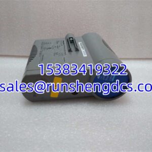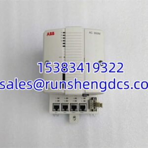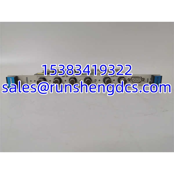
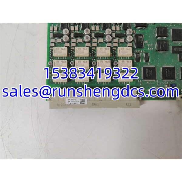

Description
Key Technical Specifications
| Parameter | Detail |
|---|---|
| Manufacturer | Vibro-Meter (Meggitt / Parker Meggitt) |
| Part Number | 200-510-076-114 |
| Product Family | VM600 MPC4 Machinery Protection Card |
| Dynamic Inputs | 4 channels (proximity, velocity, accelerometer) |
| Speed/Phase Inputs | 2 tachometer channels |
| Signal Processing | DSP: filtering, integration/differentiation, RMS/peak, order tracking |
| Required Pairing | IOC4T or IOC4S interface card (rear-mounted) |
| Analog Outputs | 4 × 4–20 mA or 0–10 V via IOC4T |
| Relay Outputs | Via IOC4T local relays or RLC16/IRC4 relay cards |
| Power Supply | Supplied by VM600 rack backplane (typically 24 VDC) |
| Rack Compatibility | VM600 ABE04x / ABE056 frames |
| Safety Versions | Standard, Isolated Circuit, and SIL variants available |
| Hot-Swap | Supported |
| Typical Applications | Turbines, compressors, generators, pumps, fans |
Product Introduction
The MPC4 is the core processing card in the Vibro-Meter VM600 Machinery Protection System. Unlike a general-purpose PLC or DCS I/O module, it is a dedicated machinery protection processor: it acquires raw vibration and displacement signals, performs real-time DSP processing, evaluates alarm/danger thresholds, and can initiate trip actions through relay outputs.
Each MPC4 card handles four dynamic channels and two tachometer/phase-reference channels. The dynamic inputs can be configured for relative shaft vibration, absolute vibration, eccentricity, thrust position, casing expansion, or dynamic pressure, depending on the sensor type and channel configuration. The tachometer inputs support eddy-current probes, magnetic pickups, and TTL signals, and can handle fractional speed ratios for multi-shaft machines.
A critical architectural point is that the MPC4 does not operate alone. It must be paired with an IOC4T or IOC4S interface card mounted at the rear of the rack. The IOC4T card provides sensor wiring terminals, buffered BNC outputs, 4–20 mA / 0–10 V analog outputs, and local relay outputs. Replacing an MPC4 without confirming the IOC4T pairing and the project configuration can result in correct power-up but incorrect trip behavior.
The 200-510-076-114 suffix identifies a specific variant. Because cards exist in Standard, Isolated, and SIL versions, and because connector board options differ across suffixes, this part number should be treated as a configured protection card rather than a generic spare.
QA/QC Transparency SOP
- Intake & Label Verification: Record full PNR 200-510-076-114, serial number, hardware revision, SIL/standard designation, and firmware version. Inspect front-panel BNC connectors, LEDs, and rear mating interface.
- Rack & Pairing Check: Confirm compatibility with the installed rack (ABE04x/ABE056) and verify the paired /IOC4S card type and revision.
- Power-Up & Self-Test: Install into a verified rack. Confirm power LED, OK system status, and absence of hardware faults after self-test.
- Channel Functional Test: Inject calibrated dynamic and tachometer signals. Verify amplitude, phase, gap voltage, and alarm/danger threshold response per channel.
- Output & Trip Verification: Confirm 4–20 mA / 0–10 V analog outputs and relay trip logic against the existing project configuration. Do not close trip loops until scaling and setpoints are validated.
- Final Documentation: Document firmware revision, channel test results, relay behavior, SIL/standard status, and any deviations. Pack with ESD and mechanical protection.
Field Engineer Gotchas
- The cannot terminate field wiring by itself. Fix: Always verify the paired interface card and its revision.
- Suffix Matters: 200-510-076-114 is not interchangeable with other suffixes without verification. Fix: Match PNR, SIL level, connector type, and firmware to the existing card.
- SIL vs. Standard Version: SIL-rated cards are used in safety-related trip functions. Fix: Do not substitute a Standard version for a SIL application without engineering approval.
- Trip Logic Must Be Validated: A card may pass self-test but still carry wrong setpoints. Fix: Compare alarm/danger thresholds, delay, latch, and speed-adaptive settings against the live database.
- Hot-Swap Is Not Risk-Free: supports hot-swap, but replacement can temporarily affect outputs. Fix: Follow site safety procedures, bypass trip logic if required, and verify channel-by-channel after insertion.
- Sensor Power Dependency: supplies power to IEPE accelerometers and proximity probe systems. Fix: Verify sensor supply voltage and loop integrity after replacement.
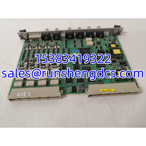
Vibro-Meter MPC4 200-510-076-114
Application Scenarios
- Steam and gas turbine protection: Monitoring shaft vibration, eccentricity, and speed with trip-grade reliability.
- Centrifugal compressor monitoring: Tracking relative vibration, thrust position, and casing expansion.
- Generator and motor protection: Detecting bearing vibration anomalies and imbalance conditions.
- Replacing failed cards while preserving existing wiring and project configuration.
FAQ
A: No. It is a dedicated machinery protection processor within the system, not a general-purpose PLC.
Q: What does 200-510-076-114 mean?
A: It is the specific part-number suffix for this card variant. The exact hardware revision, SIL rating, and connector configuration must be confirmed from the physical label.
A: Not automatically. The PNR suffix, SIL level, firmware, and pairing must match the installed system.
A: Yes. requires a paired /IOC4S interface card for sensor wiring, analog outputs, and relay outputs.
Q: What sensors does it support?
A: Proximity probes, velocity sensors, IEPE accelerometers, and related vibration/displacement transducers compatible with .
Q: What should I check before buying surplus?
A: Full PNR 200-510-076-114, SIL/standard version, hardware/firmware revision, physical condition, compatibility, and availability of the correct project configuration.