Description
Key Technical Specifications
| Parameter | Value |
|---|---|
| Channels | 4 isolated analog input + 4 isolated excitation |
| Isolation Rating | 250 Vrms (channel-to-channel and channel-to-chassis) |
| Input Impedance | 1 GΩ (normal), 50 kΩ (powered off/overload) |
| Gain Settings | 1, 2, 5, 10, 20, 50, 100, 200, 500, 1000, 2000 (jumper-selectable) |
| Input Range | ±2.5 mV to ±5 V (depending on gain) |
| Excitation Outputs | 4 isolated excitation channels (voltage or current) |
| Output Modes | Parallel (4 channels to 4 DAQ inputs) or Multiplexed (4 channels to 1 DAQ input) |
| Low-Pass Filter | Per-channel, built-in |
| Shunt Calibration | Supported via SCAL control line |
| Cold Junction Compensation | Supported via terminal block temperature sensor (mtemp/dtemp) |
| Compatible Chassis | SCXI-1000 and other SCXI-compliant chassis |
| Compatible DAQ Boards | MIO-16 series (full functionality), Lab-PC+ (single-chassis only) |
Product Introduction
You wire a strain gauge into a DAQ board and get noise, drift, and ground loops. The SCXI-1121 sits between the sensor and the digitizer, doing the heavy lifting — amplifying microvolt-level bridge outputs, rejecting common-mode voltage up to 250 Vrms, and giving each channel galvanic isolation so one bad ground doesn’t corrupt the whole rack.
This module handles a wide sensor menu: strain gauges (quarter, half, and full bridge), RTDs, thermistors, thermocouples, millivolt sources, and 4–20 mA / 0–20 mA current loops. Each of the four channels has its own independently jumper-configurable amplifier, filter, and excitation source. You can run all four channels in parallel to four separate DAQ inputs, or multiplex them into a single DAQ channel to scale up channel count across multiple SCXI-1121 modules. Bottom line — if your measurement chain involves weak differential signals in electrically noisy environments, this is the conditioning front-end NI designed for exactly that job.
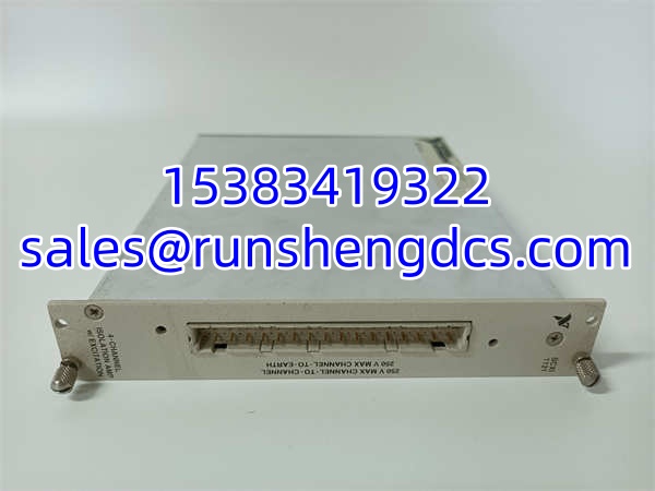
NI SCXI-1121
QA/QC Transparency SOP
For surplus or pulled SCXI-1121 modules, here is a practical validation sequence:
- Intake & Origin Verification — Confirm the silkscreen reads SCXI-1121. Check for the NI logo, part number, and serial/date codes. Inspect the SCXI edge connector for bent or corroded pins. Any module with re-marked labels gets flagged.
- Live Functional Testing — Seat the module in a powered SCXI chassis (e.g., SCXI-1000). Connect a known DAQ board (MIO-16 series preferred). Apply a calibrated voltage source to each input channel at multiple gain settings. Verify the digitized reading matches the expected value within the module’s specified accuracy band.
- Electrical Parameter Tests — Measure isolation resistance between channels and from channel to chassis ground using a megger (do not exceed the 250 Vrms rating during testing). Check excitation output voltage accuracy on all four excitation channels. Verify input impedance is in the 1 GΩ range when powered on.
- Firmware/Config Verification — Read the module identification through NI-DAQmx or Traditional NI-DAQ in Measurement & Automation Explorer (MAX). Confirm the module is recognized correctly. Back up any jumper configuration documentation for the end user.
- Final QC & Anti-Static Packaging — Clear all test connections. Seal in an ESD-safe bag with desiccant. Label with part number, serial number, test date, and pass/fail status.
Field Engineer Gotchas
- Gain jumpers will bite you. The SCXI-1121 uses physical jumpers to set gain on each channel. If a previous user set Gain = 100 and you plug in expecting unity gain, your readings will be 100× off. Always check and document jumper positions before connecting sensors. I’ve seen engineers spend an afternoon chasing a “broken DAQ” that was just a jumper left from the last configuration.
- Multiplexed mode has DAQ board limitations. Not every DAQ board can scan the SCXI-1121 in multiplexed output mode. Boards like the Lab-PC, Lab-NB, and Lab-LC can only do single-channel reads in mux mode — they cannot drive the internal multiplexer scan sequence. If you need multiplexed scanning, verify your DAQ board supports it in the NI documentation before wiring anything up.
- This is NOT a digital I/O module. The is strictly analog input. It cannot output square waves, drive solenoids, or perform digital I/O. If you need pulse generation or digital control, you need a different SCXI module (like the SCXI-1180 feed-through for counter access) or a dedicated counter/timer board.
- Excitation channel loading matters. The four isolated excitation channels have current limits. If you wire a low-impedance bridge that draws more excitation current than the channel can supply, your readings will sag and drift. Check your sensor’s bridge resistance against the excitation voltage you’ve selected.
- Terminal block CJC jumper confusion. The cold junction compensation temperature sensor on the terminal block can be read in multiplexed mode (mtemp) or direct mode (dtemp) depending on jumper position. Get this wrong and your thermocouple readings will have no CJC correction — meaning they’ll be off by several degrees depending on ambient temperature.
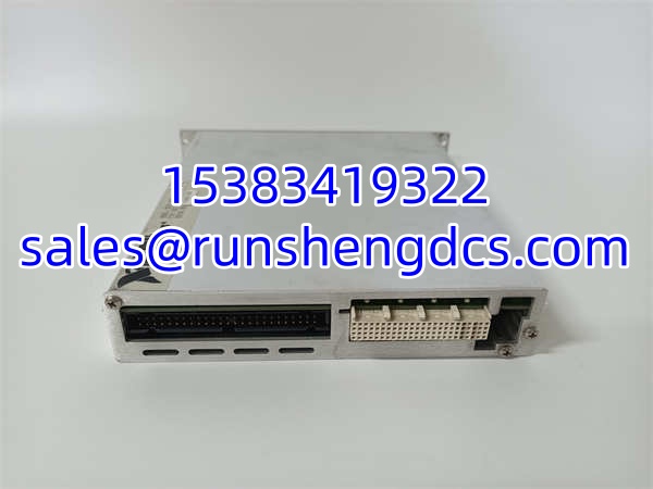
NI SCXI-1121
Application Scenarios
- Structural strain measurement — Quarter, half, and full bridge strain gauge configurations on test specimens, bridges, or pressure vessels where microvolt-level signals need amplification and common-mode rejection.
- Industrial process monitoring — 4–20 mA and 0–20 mA current loop signals from field transmitters in environments with high common-mode voltage, where ground isolation prevents measurement corruption.
- Laboratory material testing — RTD and thermocouple inputs on tensile test rigs or thermal cycling chambers, with per-channel isolation preventing cross-talk between heated and reference zones.
- Multi-point temperature arrays — Multiple modules multiplexed into a single DAQ channel to digitize dozens of thermocouple or RTD inputs through one analog-to-digital converter.
FAQ
No. It requires a DAQ board that supports the SCXI interface protocol. The MIO-16 series gives full functionality. Older boards like Lab-PC+ work in single-chassis setups only. Check the NI compatibility list for your specific DAQ hardware before purchasing.
Does this module support hot-swapping?
No. SCXI modules are not designed for hot-swap. Power down the chassis before inserting or removing the module.
What chassis do I need?
Any SCXI-compliant chassis — the SCXI-1000 is the most common. The chassis provides power and the backplane bus that connects the module to your DAQ board.
You can install multiple modules in the same chassis and multiplex their outputs into a single DAQ channel, which effectively scales your channel count. But “daisy-chaining” across separate chassis requires specific SCXI interconnect cabling and DAQ board support.
The SCXI platform is a legacy NI product line. NI has shifted focus to newer platforms (PXI, CompactDAQ, cDAQ). modules are available through surplus and third-party channels, but long-term OEM support is limited. Plan your migration path accordingly.
What terminal block do I need?
The SCXI-1320 or SCXI-1321 terminal blocks are commonly paired with the . The terminal block provides screw terminals for sensor wiring and includes the CJC temperature sensor for thermocouple compensation. Verify the terminal block part number against your specific wiring needs.
Can this module handle 4–20 mA current loops directly?
Yes. The accepts 4–20 mA and 0–20 mA current inputs. You will typically need a precision shunt resistor to convert the current signal to a voltage that the module can read, unless you are using the module’s built-in current input configuration. Check the user manual for the exact wiring topology.