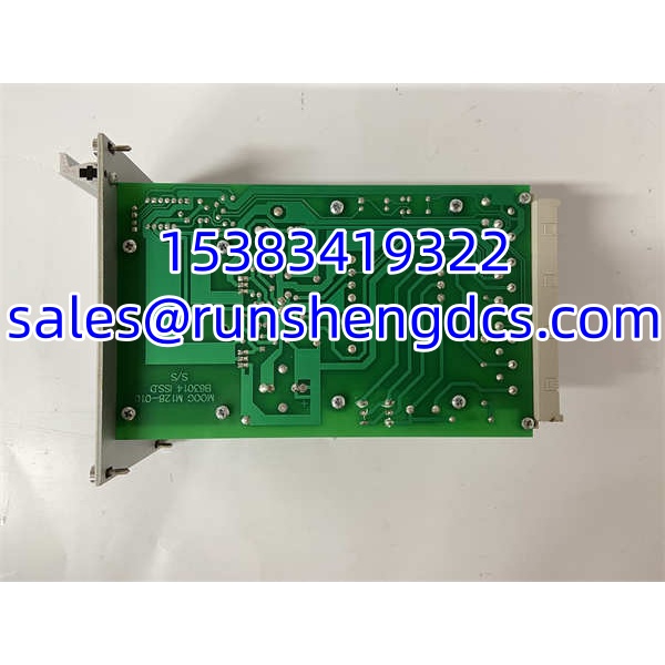

Description
Key Technical Specifications
| Parameter | Specification |
|---|---|
| Manufacturer | MOOG |
| Model | M128-010 / M128-010-A001B |
| Product Type | Servo valve driver / hydraulic servo amplifier |
| Control Function | Closed-loop servo/proportional valve control |
| Power Supply | 24 VDC nominal |
| Command Input | Analog ±10 V typical |
| Valve Output | Current output to torque-motor servo/proportional valve |
| Feedback | LVDT / spool-position feedback (variant dependent) |
| Diagnostics | Status LEDs and test points |
| Mounting | Panel mount; DIN-rail with adapter in many cases |
| Operating Temperature | 0 to +50 °C typical |
| Environment | Industrial hydraulic / high-EMI cabinets |
Product Introduction
In hydraulic motion loops, the valve driver is usually the quietest component — until it is not. The MOOG M128-010 / M128-010-A001B sits between the controller and the servo valve, converting a ±10 V command into a controlled valve current while using LVDT or spool-position feedback to keep the loop stable.
It is commonly used where position repeatability, low drift, and fast response matter: press cushion control, roll-gap adjustment, injection molding axes, hydraulic test stands, and aerospace actuation benches. The 24 VDC supply keeps cabinet power simple, and the onboard LEDs help technicians separate wiring faults from tuning problems. Treat the A001B suffix as meaningful: feedback scaling, diagnostic options, or commissioning interface details can vary between sub-revisions, so always match the nameplate before replacing a failed unit.
QA/QC Transparency SOP
- Intake & Origin Verification — Confirm full model code M128-010-A001B. Inspect connectors, terminal blocks, and PCB for heat damage, corrosion, or moisture ingress.
- Power-Up Diagnostics — Apply 24 VDC and verify normal LED status. Check for fault indication before connecting a valve.
- Signal Path Test — Apply a calibrated ±10 V command and measure valve current output. Verify linearity, zero offset, and response stability.
- Feedback Loop Verification — Connect a compatible LVDT/spool-position feedback signal. Confirm closed-loop operation with no hunting or oscillation at low flow.
- Final QC & Packaging — Record command scaling, zero offset, feedback calibration, and LED status. Ship in ESD-safe packaging with connector caps installed.
Field Engineer Gotchas
- Not a Servo Motor Drive — The M128-010 drives servo valves, not servo motors. If the application is electric motion control, this is the wrong hardware.
- A001B Suffix Matters — Sub-revisions can change feedback scaling, diagnostic behavior, or commissioning options. Do not subute variants without confirming the valve and feedback configuration.
- LVDT/Spool Feedback Must Match — If the feedback type or scaling is wrong, the loop will oscillate, drift, or fail to close. Verify sensor wiring and calibration before tuning.
- ±10 V Command Offset — A small offset at the command input can cause unwanted valve creep. Zero the input at the controller and check the driver’s null adjustment.
- Noise in Hydraulic Cabinets — Solenoid contactors, pump starters, and VFDs can inject noise into analog signals. Use shielded cables, single-point grounding, and keep analog wiring away from power cables.
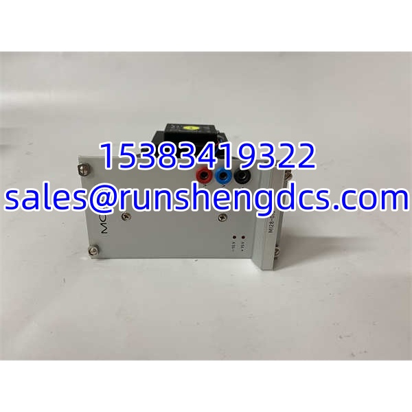
MOOG M128-010 M128-010-A001B
Application Scenarios
- Press cushion pressure control — A PLC sends ±10 Vthe , which drives a MOOG servo valve. LVDT feedback keeps cushion position stable during forming cycles.
- Hydraulic test stand — The driver provides low-drift current control for precise flow positioning, improving repeatability during component qualification.
- Roll-gap or tension control — In metal or paper processithe closes the valve loop to maintain consistent gap or web tension despite pressure fluctuations.
FAQ
A: No. It is a servo valve driver for hydraulic control, typically used with MOOG torque-motor servo valves.
Q: Can it run without LVDT feedback?
A: Some variants support open-loop proportional control, but closed-loop LVDT/spool feedback is the primary design intent. Confirm the exact variant capability in the MOOG datasheet.
Q: What voltage does it require?
A: Typically 24 VDC nominal. Verify the nameplate and power budget before installation.
Q: Is it compatible with PLC analog outputs?
A: Yes, if the PLC provides a ±10 V analog command. Ensure signal ground is handled correctly to avoid offset or noise.
A: Only after confirming feedback type, command scaling, and diagnostic options. The A001B suffix should be matched whenever possible.
Q: Where can I find the official datasheet?
A: Request the MOOG series datasheet directly from MOOG or an authorized distributor. Public listings often omit revision-level details needed for safe replacement.