Description
Key Technical Specifications
| Parameter | Value |
|---|---|
| Manufacturer | GE / GE Fanuc Automation |
| Model | VMIVME-4140 |
| Product Type | 32-channel 12-bit analog output VMEbus module |
| Bus Standard | VMEbus, 6U single-slot module |
| Channel Count | 32 independent analog outputs |
| Resolution | 12-bit per channel |
| Output Ranges | ±10 V, ±5 V, ±2.5 V; 0–10 V, 0–5 V, 0–2.5 V (software-selectable) |
| Output Current | ±10 mA per channel |
| Output Impedance | 0.8 Ω |
| Update Mode | Random (non-scanned) update; dual-buffered synchronous update |
| Calibration | Auto-calibration via system reset or software command |
| Self-Test | Automatic self-test after reset; front-panel status LED |
| Connectors | Front-panel analog output connectors; isolated BNC reference access |
| Field Isolation | Output can be disconnected from field wiring for offline testing |
| Power | +5 VDC from VME backplane |
| Operating Temperature | Typically 0 to 55 °C; verify per exact suffix |
| Addressing | Hardware jumper-configured VME base address |
| Data Format | Binary or offset binary, software configurable |
Product Introduction
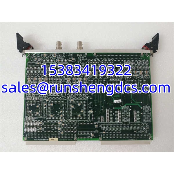
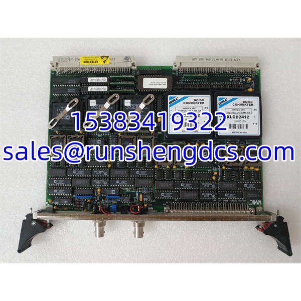
In legacy VME-based control racks, analog output boards are often the hardest cards to replace because the application depends on exact channel count, update behavior, and calibration stability. The GE VMIVME-4140 is a 32-channel, 12-bit analog output module built for VMEbus systems. Each channel has its own DAC, which prevents scan-dependent channel skew and makes it suitable for multi-loop control, actuator positioning, test stimulation, and coordinated analog setpoint distribution.
It supports six software-selectable voltage ranges, dual-buffered synchronous updates, and automatic calibration with stored offset/gain correction tables. The front-panel reference BNC and field-disconnect capability are useful during commissioning and offline verification. Bottom line — it is a solid legacy AO board for VME systems, but it is not a CPU, fieldbus adapter, or motion pulse card. Verify the exact suffix and driver support before integrating it into a live rack.
GE VMIVME-4140
QA/QC Transparency SOP
- Intake & Origin Verification
Confirm model VMIVME-4140, exact suffix (-000 / -001), label condition, VME connector pins, and front-panel DB connectors. Reject units with bent P1/P2 pins or corroded analog terminals. - Live Functional Testing
Install in a compatible VME crate with +5 VDC backplane power. Verify board recognition, self-test LED behavior, and absence of immediate bus faults. - Analog Output Verification
Select a known voltage range. Command mid-scale, full-scale, and zero outputs on sample channels. Measure output voltage, current capability, and 0.8 Ω output impedance behavior under light load. - Calibration & Self-Test Check
Run auto-calibration via software or reset. Confirm calibration table generation and stable output after calibration. Verify self-test pass status. - Final QC & Anti-Static Packaging
Apply ESD bag, foam protection, and verified model/suffix label. Include tested channel summary, voltage range confirmation, and a compatibility warning.
Field Engineer Gotchas
- Misidentified as CPU or pulse card
Risk: Some surplus listings label VMIVME-4140 as a CPU board or pulse-control module.
Solution: Confirm it is the 32-channel 12-bit analog output board.
Blunt warning: If the listing mentions Ethernet, Profibus, Modbus, or PowerPC CPU, walk away unless you can verify the OEM label. - Wrong suffix assumption
Risk: -000 and -001 may differ in calibration tables, connector options, or firmware.
Solution: Match the exact suffix to the existing board and driver set.
War story: A test rack accepted a replacement board physically, but the driver failed to initialize because the suffix and firmware did not match the installed software package. - Load impedance mismatch
Risk: The board sources/sinks ±10 mA with 0.8 Ω output impedance. Driving low-impedance loads can cause range errors.
Solution: Verify field load impedance before connecting all 32 channels.
Quick check: If outputs sag under load, measure the loop resistance before blaming the DAC. - VME address conflict
Risk: Incorrect jumper settings can conflict with other VME modules.
Solution: Document the base address and address modifier before removing the original board.
Field note: A replaced board powered up but never responded because the address jumpers were still in the default position. - Driver and OS compatibility
Risk: is a legacy board. Modern OS support may be limited.
Solution: Confirm driver availability for the target controller or real-time OS before procurement.
GE VMIVME-4140
Application Scenarios
- Legacy VME-based process control
Provides multiple analog setpoints to valve positioners, actuators, and signal converters in older control racks. - Automated test equipment
Generates coordinated analog stimuli across 32 channels for calibration benches and functional test systems. - Motion and actuator control interfaces
Supplies ±10 V command signals to servo amplifiers, hydraulic controllers, or analog drive inputs. - Research and simulation platforms
Used where deterministic dual-buffered updates are needed across many analog channels.
FAQ
No. It is a 32-channel, 12-bit analog output VMEbus module. Listings describing it as a CPU or pulse card are typically incorrect.
How many analog outputs does it provide?
32 independent 12-bit analog output channels, each with its own DAC.
What voltage ranges are supported?
±10 V, ±5 V, ±2.5 V, 0–10 V, 0–5 V, and 0–2.5 V, software-selectable per configuration.
Can all channels update simultaneously?
Yes. It supports dual-buffered synchronous update via software or external trigger.
Does it support 4–20 mA output directly?
Not natively as a current loop output. It is primarily a ±10 V-class voltage output board. External converters may be required for 4–20 mA loads.
Is it still supported by GE?
VMIVME/VMIC products are legacy. Support paths may now fall under Emerson or third-party surplus channels. Verify driver availability before deployment.
Can it be hot-swapped?
VMEbus hot-swap capability depends on the crate, backplane, and system design. Do not assume hot-swap support without confirming the rack specification.