
Description
Key Technical Specifications
| Parameter | Specification |
|---|---|
| Manufacturer | GE (General Electric) |
| Model | IS215UCVGH1A |
| Product Type | Universal Control VME (UCV) CPU / Processor Board |
| System Platform | GE Speedtronic Mark VI IS200 Series Turbine Control System |
| Processor | Intel ultra-low-voltage Celeron 650 |
| Memory | 128 MB SDRAM |
| Storage | 128 MB flash memory |
| Ethernet Ports | Dual stacked RJ45 (labeled LAN1 and LAN2) |
| Serial Ports | 2× COM ports (labeled 1 and 2, side by side) |
| Video Output | SVGA monitor port (behind front-panel reset switch) |
| USB Ports | 2× separate USB connectors |
| Peripheral Interface | Keyboard/mouse port (PS/2-style) |
| Front Panel Features | Reset switch, 4 status LEDs, panel opening for auxiliary card access |
| Chassis Compatibility | Standard Mark VI VME rack (13-slot or 21-slot) |
| Backplane Interface | VME bus connector with vertical and right-angle pin connectors |
| Auxiliary Card Support | Provisions/standoffs for add-on daughterboards |
| Country of Origin | USA |
| Product Status | Legacy/discontinued (no longer in production by GE) |
| Warranty (distributor) | Typically 12 months from acceptance (varies by supplier) |
Product Introduction
The GE IS215UCVGH1A is the single-slot Universal Control VME (UCV) controller board for GE’s Speedtronic Mark VI gas and steam turbine control system. It serves as the central processing unit of the Mark VI turbine controller, executing the real-time control logic that governs fuel flow, speed regulation, temperature monitoring, vibration protection, and trip functions for both simple-cycle and combined-cycle turbine installations.
At the heart of the IS215UCVGH1A is an Intel ultra-low-voltage Celeron 650 processor, paired with 128 MB of SDRAM for runtime execution and 128 MB of flash memory for storing the control application, configuration data, and firmware. This combination provides sufficient processing power and storage for the deterministic, millisecond-level response requirements of turbine control — while the low-voltage design helps reduce heat generation inside the sealed VME chassis, a critical consideration in power plant control rooms where ambient temperatures can run high.
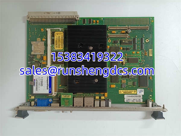
The front panel of the IS215UCVGH1A is designed for both engineering access and operational visibility. It features a reset switch (with an SVGA monitor port located directly behind it), a keyboard/mouse port for local HMI connection, two COM ports (labeled 1 and 2) for serial communication with field devices or legacy equipment, two stacked Ethernet ports (LAN1 and LAN2) for network connectivity to the plant DCS, engineering workstation, or redundant controller peer, two USB connectors for peripheral connection or data export, and four status LEDs that provide at-a-glance health indication (typically power, run, fault, and communication status). A panel opening allows access to auxiliary daughterboards that may be mounted on the main processor board.
One of the most important practical features of the IS215UCVGH1A is its backward compatibility. GE released five revisions of the UCV controller for the Mark VI system, and the IS215UCVGH1A is designed as a direct drop-in replacement for any prior UCV revision. If you are replacing an older controller board in an existing Mark VI rack, you do not need to upgrade the backplane or modify the chassis — simply remove the old board, insert the into the same VME slot, and download the existing application configuration. This makes it an ideal choice for obsolescence management and life-extension projects on aging turbine installations.
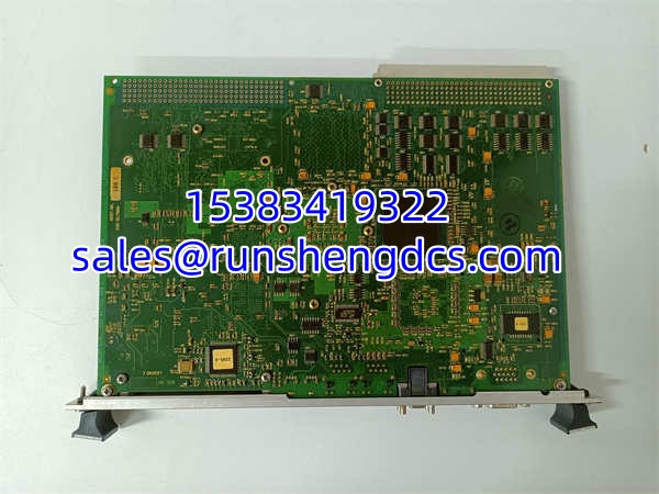
The board is constructed with multiple auxiliary sub-boards mounted on the main PCB, with standoffs provided to accept additional daughterboards as needed. The PCB itself carries capacitors, inductor coils, crystal oscillators, oscillator chips, jumper switches, integrated circuits, and other surface-mount and through-hole components typical of industrial-grade controller hardware. The VME bus connector uses both vertical pin connectors (for the main backplane interface) and right-angle pin connectors along the board edge (for auxiliary signal routing), ensuring a robust mechanical and electrical connection to the rack.
As with all Mark VI components, the is designed for the harsh electromagnetic and thermal environment of power generation facilities. The board’s components are selected and tested for industrial temperature ranges, and the conformal coating protects against condensation and oil mist ingress — common failure modes in turbine control cabinets located adjacent to the turbine deck.
The is a legacy component that is no longer in production by GE. It is available through authorized surplus distributors and industrial automation spare parts suppliers, typically as new old stock (NOS) or factory-refurbished units. When sourcing replacements, always verify the board’s revision level and ensure it matches your Mark VI system’s firmware compatibility requirements.
QA/QC Transparency SOP
- Intake & Visual Inspection: Each board is inspected for physical damage — cracked PCB substrate, burned or discolored components (especially around the voltage regulation and flash memory sections), corroded front-panel connectors (Ethernet, COM, USB, SVGA, keyboard/mouse), bent VME backplane pins, or signs of moisture ingress (white residue on conformal coating). Units with charred components, swollen capacitors, or damaged connector housings are rejected.
- VME Backplane Pin Continuity Check: Using a multimeter, we verify continuity on all pins of the VME backplane connector (both vertical and right-angle connectors) to ensure no open circuits or cold solder joints. Bent or missing pins are grounds for rejection, as they can cause intermittent communication with the VME backplane or loss of power to the board.
- Front-Panel Connector Verification: Each front-panel connector is tested for mechanical integrity and electrical continuity:
- Dual Ethernet (LAN1/LAN2): RJ45 pins checked for correct pinout and continuity; link LEDs verified to illuminate when connected to a live network switch.
- COM Ports 1 & 2: RS-232 signal levels verified on TX, RX, RTS, CTS, DTR, DSR, DCD, and GND pins.
- SVGA Port: 15-pin D-sub connector pins checked for continuity; video output verified with a test monitor.
- USB Ports: Power and data lines (D+/D-) checked for continuity; device enumeration verified with a USB flash drive.
- Keyboard/Mouse Port: PS/2 clock and data lines checked for continuity.
- Processor & Memory Functional Test: The board is installed in a Mark VI VME test rack and powered up. We verify that the Intel Celeron 650 processor boots correctly, the BIOS POST completes without errors, and the operating system loads from flash memory. We run a memory test to verify all 128 MB of SDRAM is accessible and error-free, and a flash memory read/write test to confirm all 128 MB of flash is functional.
- Ethernet Communication Test: Both LAN1 and LAN2 ports are connected to a test network switch. We verify that the board obtains an IP address (via DHCP or static configuration), can ping the engineering workstation, and can establish a TCP/IP connection for application download. Link speed and duplex settings are verified.
- Serial Port Loopback Test: COM ports 1 and 2 are tested using a loopback plug. We send a known data pattern out of the TX pin and verify it is received correctly on the RX pin at multiple baud rates (9600, 19200, 38400, 57600, 115200). RTS/CTS hardware flow control is verified if supported.
- Front-Panel LED & Reset Switch Test: All four status LEDs are verified to illuminate correctly during boot and during normal operation. The reset switch is tested to confirm it triggers a hard reset of the processor when pressed.
- Final QC & Anti-Static Packaging: After passing all tests, the board is placed in an anti-static bag with desiccant and shipped in a rigid box with foam inserts to protect the front-panel connectors and VME backplane pins. A test report with channel-by-channel verification is included.
Field Engineer Gotchas
- Direct replacement, but verify firmware compatibility: The is marketed as a drop-in replacement for all prior Mark VI UCV revisions. However, the control application firmware loaded on the flash memory must be compatible with your specific Mark VI system’s I/O card set and turbine configuration. If you are replacing a board in an existing system, always back up the existing application configuration before swapping boards. If the new board comes with a different firmware version, you may need to download your existing application from the engineering workstation.
- Flash memory degradation over time: The 128 MB flash memory on the is a finite-write medium. If your system performs frequent configuration changes or data logging to flash, the memory cells can wear out over time. If the board fails to boot or reports flash memory errors during POST, the flash may have reached its end of life. In this case, the board may need to be sent to a repair facility for flash chip replacement and reprogramming.
- VME slot seating and retention: The is a heavy board with multiple connectors and daughterboards. When inserting it into the VME chassis, ensure the board is fully seated in the slot guides before applying pressure to the front-panel retention screws. Forcing a misaligned board can bend the VME backplane pins, which are difficult and expensive to repair. Always use the top and bottom retention screws to secure the board after insertion.
- Ethernet port labeling confusion: The two stacked Ethernet ports are labeled LAN1 and LAN2. In redundant Mark VI configurations, LAN1 is typically used for the primary control network and LAN2 for the secondary/redundant network. Ensure your network cabling matches the configuration in your control application — swapping and can cause communication failures with the DCS or redundant peer controller.
- COM port pinout verification: The two COM ports are RS-232 serial ports, but the pinout may vary depending on the specific application (full RS-232 vs. 3-wire TX/RX/GND only). If you are connecting a legacy field device or a serial-to-Ethernet converter, verify the pinout matches your device’s requirements. A mismatched pinout can result in no communication or, in the worst case, damage to the COM port driver IC.
- SVGA port access requires removing the reset switch cover: The SVGA monitor port is located behind the front-panel reset switch. To connect a monitor, you must carefully remove or pivot the reset switch cover. Be gentle — the reset switch mechanism is fragile and can break if forced. After connecting the monitor, ensure the reset switch cover is properly reinstalled to maintain the front panel’s EMI shielding.
- Auxiliary daughterboard compatibility: The has standoffs for auxiliary daughterboards, but not all daughterboards are compatible with all UCV revisions. If your existing board has a daughterboard installed, verify that the replacement supports the same daughterboard. Some distributors sell the without the daughterboard — if your application requires it, you will need to source it separately or transfer it from the old board.
- Conformal coating inspection in oil mist environments: Like all Mark VI boards, the has a conformal coating to protect against condensation and oil mist. However, in turbine control cabinets located near the turbine deck, oil mist can accumulate on the board over time and degrade the coating. If you see signs of coating degradation (cracking, peeling, or discoloration), consider having the board professionally recoated or replacing it proactively during a planned outage.
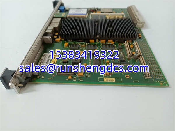
GE IS215UCVGH1A C VMIVME-7666-111000350-017666-111000 C
Application Scenarios
- Simple-cycle gas turbine control: In a 50 MW simple-cycle gas turbine installation, the serves as the primary controller executing the speed and load control logic. It reads turbine speed from magnetic pickups via the Mark VI I/O packs, calculates the required fuel flow based on the speed error, and outputs the fuel command to the electro-hydraulic servo valves. The dual Ethernet ports connect to the plant DCS for remote monitoring and to the engineering workstation for configuration changes. The COM ports may be used to communicate with a legacy governor panel or a serial-connected HMI.
- Combined-cycle gas turbine (CCGT) multi-shaft control: In a 1-on-1 combined-cycle plant (one gas turbine, one heat recovery steam generator, one steam turbine), the in the gas turbine controller communicates with the steam turbine controller via the Ethernet network. The gas turbine controller sends exhaust temperature and load data to the steam turbine controller, which uses this information to optimize steam production and turbine loading. The ‘s dual Ethernet ports allow it to maintain separate communication channels for the inter-turbine network and the plant DCS network.
- Steam turbine retrofit in a coal-fired power plant: In a coal-fired power plant undergoing a turbine control system upgrade, the replaces an older Mark V or early Mark VI controller. The drop-in compatibility means the existing VME chassis, backplane, and I/O cards can be retained, significantly reducing the scope and cost of the upgrade. The new board’s improved processing power and memory allow for more sophisticated control algorithms, such as adaptive gain scheduling for improved part-load efficiency.
- Marine gas turbine propulsion control: In a naval or commercial vessel powered by a marine gas turbine (derived from an aero-derivative design), the provides the propulsion control logic. The board’s low-voltage Celeron processor is well-suited for the marine environment, where power quality can be variable and heat dissipation is challenging. The dual Ethernet ports provide redundancy for communication with the ship’s integrated platform management system (IPMS), ensuring that loss of one network does not result in loss of propulsion control.
FAQ
A: No. The is designed specifically for the Mark VI IS200-series VME chassis. Mark VIe systems use a different architecture (IS220/IS230-series cards) and are not compatible with the . If you need a replacement controller for a Mark VIe system, you would need an IS220/IS230-series CPU card, not the .
A: Not directly. Mark V systems use the DS200-series card architecture, which is mechanically and electrically incompatible with the Mark VI VME chassis. Upgrading from Mark V to Mark VI requires a full chassis and I/O card replacement, not just a CPU board swap. The is only compatible with existing Mark VI VME racks.
A: Both are Mark VI UCV controller boards, but they represent different hardware revisions. The is the single-slot version that serves as a direct replacement for all prior UCV revisions. The IS215UCVGM06A is another revision in the UCV family. When ordering a replacement, always verify which revision is currently installed in your system and confirm compatibility with your control application firmware. In most cases, the can replace earlier revisions, but always consult the GE Mark VI hardware reference manual or your system integrator before making a substitution.
A: The control application is downloaded from the GE ToolboxST (or legacy Mark VI configuration software) engineering workstation via the Ethernet network. Connect your engineering laptop to the or port on the , launch the configuration software, and use the download function to transfer the application to the board’s flash memory. Ensure the board has booted successfully and is communicating with the engineering workstation before attempting the download.
A: It depends on your specific Mark VI configuration. Some Mark VI installations use the UCV controller without any auxiliary daughterboards, while others require specific daughterboards for additional functionality (e.g., additional serial ports, specialized communication interfaces). If your existing board has a daughterboard installed, check the Mark VI hardware manual to determine whether the daughterboard is required for your application. If it is, you will need to either transfer the daughterboard from the old board to the new or source a compatible daughterboard separately.
A: The is a legacy component that was originally designed for a 15–20 year service life in industrial environments. However, actual lifespan depends heavily on operating conditions — ambient temperature, humidity, oil mist exposure, and power quality all affect longevity. Boards installed in well-maintained control cabinets with proper air filtration and temperature control can last 20+ years. Boards exposed to oil mist, high temperatures, or frequent power cycling may fail sooner. If your board has been in service for more than 15 years, consider proactive replacement during a planned outage rather than waiting for an in-service failure.
A: Since the is no longer in production by GE, it is available through authorized surplus distributors and industrial automation spare parts suppliers. Reputable suppliers include AX Control, Shenzhen Changxin Automation, Xiamen XiongBa E-Commerce, and other specialized industrial surplus dealers. Always verify the supplier’s reputation, warranty terms (typically 12 months), and return policy before purchasing. Request a test report and photos of the actual board before committing to a purchase.