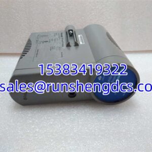
Description
Key Technical Specifications
| Parameter | Specification |
|---|---|
| Manufacturer | GE (General Electric) |
| Model | IS200SPIDG1ABA |
| Product Type | Profibus-DP Terminal Adapter Board (Gateway Interface Module) |
| System Platform | GE Speedtronic Mark VI / Mark VIe Turbine Control System |
| Companion Master Card | IS220PPRFH Profibus Master Processor Card |
| Country of Origin | USA |
| Primary Function | Routes internal Profibus DP signals to external DB9 port; provides signal conditioning, surge protection, electrical isolation, and bus fault alarm relay output |
| Profibus Interface | DB9 female connector; supports 9.6 kbps to 12 Mbps baud rate; up to 125 slave devices per segment |
| Backplane Interface | 64-pin DIN connector (direct plug-in to IS220PPRFH master card) |
| Power Supply | DC 24 V wide-range (18–32 V); typically draws 0.8 A, max 1.2 A |
| Channel Isolation | 1000 VAC isolation between bus and system backplane |
| ESD Protection | ±15 kV |
| EMC Filtering | Industrial Grade A EMI filtering |
| Fault Alarm Output | Dry-contact relay output for bus break, short circuit, slave loss — connects to DCS SOE (Foxboro FDC280, DeltaV VE3008, etc.) |
| Diagnostic Indicators | Dual LEDs: Power OK, Profibus Communication Fault |
| Operating Temperature | -25°C to +70°C (with condensation-resistant conformal coating for oil mist and high-EMI environments) |
| Installation | Standard VME single-slot chassis plug-in; metal bracket reinforcement for vibration resistance |
| Dimensions | Approx. 120 mm H × 80 mm W × 30 mm D |
| Weight | Approx. 1.2 kg |
| Configuration Software | ToolboxST (supports DP-V0/DP-V1; configure slave addresses, communication cycle for millisecond-level response) |
| Product Status | Legacy/discontinued (no longer in production by GE) |
| Warranty (distributor) | Typically 12 months from acceptance (varies by supplier) |
Product Introduction
The GE IS200SPIDG1ABA is a Profibus-DP terminal adapter board engineered specifically for the GE Speedtronic Mark VI and Mark VIe gas and steam turbine control systems. Rather than functioning as a standalone controller or generic I/O card, the IS200SPIDG1ABA serves as the critical physical and electrical interface between the IS220PPRFH Profibus master processor card (installed in the turbine control rack) and the field-level Profibus DP network that connects to third-party devices — Woodward MicroNet governors, ABB UNITROL exciters, Multilin 845EP transformer protection relays, remote Profibus I/O stations, and other field equipment.
At its core, the board solves a practical engineering problem: the IS220PPRFH master card’s Profibus DP signals are internal to the VME chassis backplane and cannot be directly wired to field cable trays. The IS200SPIDG1ABA plugs directly into the IS220PPRFH via a 64-pin DIN connector, routes the DP bus signals out through a ruggedized DB9 female connector on the front panel, and provides a clean, serviceable termination point for the shielded Profibus DP field cable. This design allows maintenance technicians to disconnect and reconnect field bus cables without removing the master card from the chassis — a significant advantage during troubleshooting or planned outages.
The board’s signal conditioning circuitry is where it earns its keep in harsh power plant environments. Built-in common-mode filtering and surge protection circuitry isolate the sensitive Mark VIe backplane electronics from the electrical noise generated by nearby generator step-up transformers, exciter cabinets, and large motor starters. The 1000 VAC channel isolation between the field bus and the system backplane ensures that a ground fault or voltage spike on the Profibus cable cannot propagate into the turbine control logic — a failure mode that could cause an unplanned turbine trip. The ±15 kV ESD protection and industrial-grade EMI filtering further harden the board against the electromagnetic environment typical of combined-cycle and simple-cycle power plants.
On the diagnostic side, the IS200SPIDG1ABA provides a dry-contact relay output that closes when the board detects a Profibus bus fault — cable break, short circuit, or slave device loss. This relay output is wired into the plant’s DCS sequence-of-events (SOE) recording system (Foxboro FDC280, DeltaV VE3008, or similar), giving operators a time-stamped record of exactly when the communication failure occurred. This is invaluable for post-trip analysis and for distinguishing between a genuine process upset and a communication-induced nuisance trip. Two front-panel LEDs provide at-a-glance status: one for power OK, one for Profibus communication fault.
Configuration is handled through GE’s ToolboxST engineering software, which allows the integrator to set the Profibus slave addresses, configure the communication cycle time (critical for meeting the millisecond-level response requirements of governor and protection devices), and enable DP-V1 acyclic data services for device diagnostics. The board supports both DP-V0 (cyclic process data only) and DP-V1 (cyclic + acyclic) modes, providing flexibility for integrating both legacy and modern Profibus devices.
One critical compatibility note: the IS200SPIDG1ABA is designed specifically to mate with the IS220PPRFH Profibus master card. It is not a standalone Profibus master and will not function without the installed in the same VME slot position. Additionally, while some distributors list this board under both Mark VI and Mark VIe series, it is primarily a Mark VIe-era component — verify the series compatibility with your specific turbine control system revision before ordering.
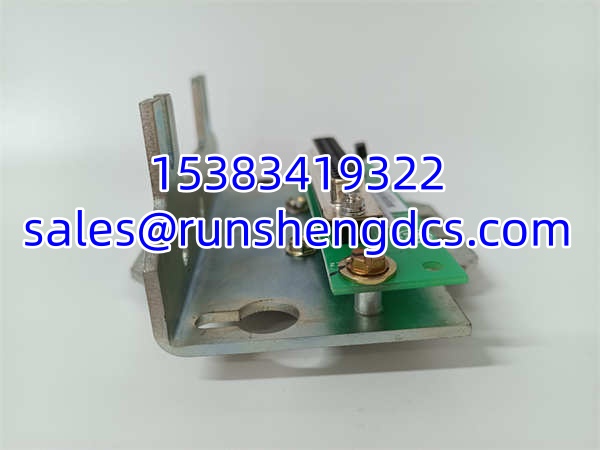
GE IS200SPIDG1ABA
QA/QC Transparency SOP
- Intake & Visual Inspection: Each board is inspected for physical damage — cracked PCB substrate, burned components on the surge protection circuit, corroded DB9 connector pins, bent 64-pin DIN backplane connector pins, or signs of moisture ingress (white residue on conformal coating). Units with charred varistors, swollen capacitors, or damaged connector housings are rejected.
- Backplane Pin Continuity Check: Using a multimeter, we verify continuity on all 64 pins of the DIN backplane connector to ensure no open circuits or cold solder joints between the master card and the terminal board. Bent or missing pins are grounds for rejection, as they can cause intermittent Profibus communication or loss of 24 V power to the board.
- DB9 Profibus Port Verification: Each of the 9 pins on the DB9 female connector is tested for correct pinout (per Profibus DP standard: pins 3/8 for data A/B, pin 5 for ground, pins 1/2/4/6/7/9 as needed for termination and shielding). We verify that the connector shell is properly grounded to the board’s metal frame for EMI shielding.
- 24 V Power Supply Test: The board is powered with a variable DC supply set to 18 V, 24 V, and 32 V to verify correct operation across the full specified range. We measure the board’s current draw at each voltage and confirm it does not exceed 1.2 A. The power OK LED is verified to illuminate at all three test voltages.
- Profibus Communication Functional Test: The board is installed with an master card in a Mark VIe test rack and connected to a Profibus DP network simulator. We verify that the master card can successfully poll slave devices through the at baud rates of 9.6 kbps, 187.5 kbps, 500 kbps, 1.5 Mbps, and 12 Mbps. Data integrity is verified by comparing transmitted and received process images.
- Isolation Resistance Test: A megohmmeter is used to verify the 1000 VAC-rated isolation between the Profibus DP field side (DB9 connector) and the system backplane side (64-pin DIN connector). Resistance must exceed 100 MΩ at 500 VDC. This test is critical — insufficient isolation can allow field-side transients to couple into the turbine control logic.
- Fault Relay Output Test: We simulate three fault conditions — Profibus cable break (disconnect the DB9 cable), short circuit (short pins 3 and 8 on the DB9 connector), and slave loss (power down a connected slave device). In each case, we verify that the dry-contact relay output closes and the communication fault LED illuminates. The relay contact resistance is measured and must be <100 mΩ when closed.
- Final QC & Anti-Static Packaging: After passing all tests, the board is placed in an anti-static bag with desiccant and shipped in a rigid box with foam inserts to protect the DB9 connector and 64-pin DIN connector. A test report with channel-by-channel verification is included.
Field Engineer Gotchas
- : The is a terminal adapter, not a Profibus master. It must be paired with the Profibus master processor card. Ordering the without the will leave you with a board that cannot initiate or manage any Profibus communication. Always verify that both boards are available before planning a replacement.
- Mark VI vs. Mark VIe compatibility confusion: Some surplus distributors list this board under both Mark VI and Mark VIe series. In reality, the is primarily a Mark VIe-era component designed for the IS200-series VME chassis. If your turbine control system is an older Mark V or early Mark VI (DS200-series), this board may not be mechanically or electrically compatible. Verify your system’s series and chassis type before ordering.
- Profibus termination resistor setting: The Profibus DP network requires proper termination at each end of the bus segment. The ‘s DB9 connector supports an external termination resistor (typically connected between pins 1 and 2, or via a dedicated termination switch on some variants). If the board is at the end of the bus segment and termination is not enabled, you will experience intermittent communication failures and slave dropouts — especially at higher baud rates (>500 kbps). Always verify the termination setting matches your network topology.
- Baud rate mismatch with slave devices: The ToolboxST configuration must set the Profibus master’s baud rate to match all slave devices on the bus. A common field error is adding a new Woodward governor (defaulting to 9.6 kbps) to a bus running at 1.5 Mbps — the new slave will not communicate, and depending on the network configuration, it can disrupt communication with all other slaves. Always verify the baud rate of each slave device before adding it to the bus.
- Cable shielding and grounding: Profibus DP communication in power plant environments is highly susceptible to EMI from generator step-up transformers, exciter cabinets, and VFDs. The shielded Profibus cable’s shield must be connected to ground at both ends (via the DB9 connector shell on the side and the slave device’s connector on the other end). A floating shield acts as an antenna and will pick up noise that corrupts the differential data signal. If you experience intermittent communication errors, check the cable shield continuity first.
- Dry-contact relay wiring polarity: The fault alarm relay output is a dry (voltage-free) contact — it does not provide any voltage. It must be wired in series with an external voltage source (typically 24 VDC from the DCS) and the DCS’s digital input module. Reversing the wiring or expecting the relay to source voltage will result in the fault alarm never being registered in the DCS. Verify the relay contact rating (typically 2 A at 30 VDC) does not exceed the connected load.
- Conformal coating degradation in oil mist environments: The board’s condensation-resistant conformal coating can degrade over time in turbine lube oil mist environments, especially if the control cabinet’s air filtration is inadequate. Degraded coating can lead to tracking between traces and eventual short circuits. If the board has been in service for more than 10 years in an oil-contaminated environment, consider replacing it proactively during a planned outage rather than waiting for a failure.
- ToolboxST DP-V1 configuration: If you are integrating devices that require DP-V1 acyclic data services (e.g., reading diagnostic parameters from a Multilin 845EP relay), you must explicitly enable DP-V1 mode in ToolboxST. The default configuration is DP-V0 (cyclic process data only), and DP-V1 devices will appear to communicate but will not provide diagnostic data. Check the device’s GSD file to confirm whether DP-V1 is required.
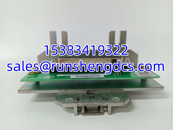
GE IS200SPIDG1ABA
Application Scenarios
- Combined-cycle gas turbine (CCGT) governor integration: In a CCGT plant, the interfaces the Mark VIe turbine controller with a Woodward MicroNet Plus governor via Profibus DP. The master card sends speed reference and load setpoint commands to the Woodward governor, and receives actual speed, load, and fuel position feedback. The ‘s isolation protects the Mark VIe backplane from the electrical noise generated by the Woodward’s power electronics. The fault relay output is wired into the plant’s DCS for SOE recording — if the Profibus communication fails, the DCS logs the event and can initiate a controlled turbine shutdown.
- Steam turbine excitation system integration: In a coal-fired power plant, the connects the Mark VIe controller to an ABB UNITROL 5000 excitation system. The Profibus DP bus carries voltage reference commands from the turbine controller to the exciter and returns generator terminal voltage, field current, and power factor readings. The board’s EMI filtering is critical here — the exciter cabinet generates significant switching noise that would otherwise corrupt the Profibus communication. The dry-contact fault relay provides a hardwired backup alarm in case the exciter loses communication with the turbine controller.
- Remote I/O station expansion: In a large industrial facility with multiple gas turbines, the is used to extend the Profibus DP network to remote I/O stations located in the turbine enclosure. These remote I/O stations collect vibration, temperature, and pressure data from sensors that are too far from the main control cabinet for direct wiring. The ‘s surge protection is essential here — the long cable runs between the control room and the turbine enclosure are vulnerable to lightning-induced transients. The board’s fault relay output alerts operators if a remote I/O station goes offline.
- Transformer protection relay integration: In a generator step-up (GSU) transformer protection scheme, the interfaces the Mark VIe controller with a GE Multilin 845EP transformer protection relay. The Profibus DP bus carries trip commands from the turbine controller to the relay and returns transformer temperature, oil level, and fault status information. The 1000 VAC isolation is particularly important in this application — a fault on the transformer’s high-voltage side can induce significant transient voltages on the low-voltage control wiring. The ‘s isolation prevents these transients from reaching the turbine control logic.
FAQ
A: Neither. The is a terminal adapter board — it is not a Profibus master or slave itself. It mates with the Profibus master processor card, which is the actual master device. The simply routes the master card’s internal Profibus signals to an external DB9 connector and provides signal conditioning and isolation. The slave devices (Woodward governors, ABB exciters, remote I/O stations, etc.) connect to the DB9 port via standard Profibus DP cables.
A: No. The is designed for the Mark VI / Mark VIe IS200-series VME chassis and the master card. Mark V systems use a different chassis architecture (DS200-series cards) and are not mechanically or electrically compatible with the . If you need Profibus DP connectivity for a Mark V system, you would need a different solution — typically a standalone Profibus master gateway mounted in the Mark V rack.
A: The Profibus DP standard allows up to 125 slave devices per segment. However, the practical limit is determined by the baud rate, cable length, and the total bus cycle time required by your application. For turbine control applications where millisecond-level response is critical (e.g., governor control), it is common to limit the number of slaves to 10–20 per segment to ensure the bus cycle time remains within the required response window. Always perform a bus cycle time calculation in ToolboxST before finalizing your network design.
Q: How do I configure the Profibus slave addresses and baud rate?
A: Configuration is done through GE’s ToolboxST engineering software. After installing the master card and terminal board, connect your engineering laptop to the Mark VIe controller’s Ethernet port and launch ToolboxST. Navigate to the Profibus configuration section, add each slave device using its GSD file, assign a unique slave address to each device, and set the bus baud rate to match all devices on the segment. Download the configuration to the master card and verify communication with each slave.
A: In most Mark VIe configurations, the can be removed and replaced without shutting down the turbine — but with an important caveat. Removing the board will interrupt Profibus communication with all slave devices on that bus segment. If those slaves include critical devices like the governor or exciter, the loss of communication may trigger a turbine trip depending on your control logic configuration. For non-critical slaves (e.g., remote I/O stations for non-essential monitoring), hot-swapping is generally safe. Always consult your plant’s turbine control logic documentation and coordinate with the operations team before performing any hot-swap procedure.