
Description
Key Technical Specifications
| Parameter | Specification |
|---|---|
| Product Model | ABB PCD231B |
| Manufacturer | ABB (Bailey Controls / INFI 90) |
| Product Category | Digital I/O Module / Excitation Controller |
| Channel Configuration | 16 Digital Inputs / 16 Digital Outputs |
| Logic Voltage | 24V DC (Compatible: 48V DC, 125V DC variants exist) |
| Output Type | Relay Contact (5A @ 250V AC) |
| Response Time | ≤ 10 ms (Scan dependent) |
| Isolation | 1500V AC Channel-to-Channel / Channel-to-Ground |
| Communication | SPI I/O Bus, Modbus, Profibus, CAN |
| Dimensions | 373mm (H) x 142mm (D) x 73.5mm (W) |
| Weight | ~1.43 kg |
| Mounting | DIN Rail / Panel Mount |
Product Introduction
Legacy PCD systems are the backbone of countless power generation and water treatment facilities, but finding reliable I/O for them is becoming a daily headache. The ABB PCD231B is the workhorse module that keeps these aging PCD controllers talking to the field, handling everything from simple pump status to complex excitation winding logic. It’s not just a generic I/O card; in many PCD configurations, the PCD231B acts as the critical interface for generator excitation control, regulating current to maintain voltage stability when the grid gets shaky.
What makes the PCD231B stick around isn’t just nostalgia; it’s the 1500V AC isolation and the ability to handle 125V DC logic in older turbine control schemes. With a response time under 10ms and relay outputs rated for 5A, it can directly drive interposing relays without needing extra signal conditioners. Just be careful with the suffix: a PCD231B101 is often tuned for excitation, while a generic PCD231B might be a standard digital I/O expander. Always verify the 3BHE025541R0101 base part number against your old card’s sticker before you pull the trigger.
QA/QC Transparency SOP
- Intake & Origin Verification: We verify the 3BHE025541R0101 base P/N and check for common PCD era defects like lifted solder joints on the heavy relay components. Visual inspection includes checking the SPI bus connector for bent pins.
- Live Functional Testing: Mounted on a PCD test rack, we force all 16 inputs and verify the SPI bus acknowledges the state change. We then energize all 16 relay outputs to confirm mechanical actuation and contact resistance <100mΩ.
- Electrical Parameter Tests: Hi-Pot test at 1500V AC between channels to verify isolation integrity. We also measure coil resistance on the output relays to detect early-stage mechanical wear.
- Firmware/Config Verification: For excitation-configured PCD231B units, we verify the internal logic map matches the B101 excitation profile. Standard I/O cards are checked for correct scan window timing parameters.
- Final QC & Anti-Static Packaging: Module is cleaned of oxidation, relay contacts are exercised 50x, and the unit is sealed in an ESD bag with desiccant. We include a test report showing the actual relay click-test results.
Field Engineer Gotchas
- The “Excitation” Trap: Not all cards are identical. The PCD231B101 has specific firmware/logic for excitation control. If you drop a standard digital I/O into an excitation slot, the controller might boot, but you’ll get “Field Current Low” alarms because the internal scaling is wrong. Always check the suffix.
- SPI Bus Termination: The communicates via the SPI I/O bus. If you’re adding this to the end of a PCD rack, ensure the termination resistor is present. I’ve seen “chattering” I/O points caused by a missing terminator on the last in the chain.
- Relay Contact Welding: These are mechanical relays, not solid-state. If you’re switching inductive loads (solenoids, contactor coils) without a snubber, you will weld the contacts. The is rated 5A resistive; inductive loads should be derated to <1A or use an interposing relay.
- Backplane Power Draw: The draws significant current when all 16 relays are energized. If you’re stacking these in a PCD rack, check your power supply margin. I’ve seen a PCD power supply sag and cause random CPU resets because someone added three cards without recalculating the load.
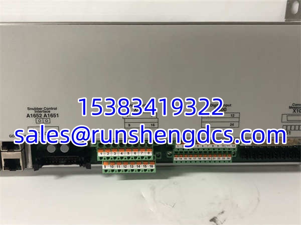
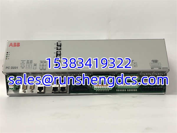
ABB PCD231B
Application Scenarios
- Generator Excitation Control: The PCD231B101 variant is the standard for regulating synchronous generator field current. It reads the AVR status and drives the field breaker/rectifier control circuits.
- Turbine Protection Logic: In legacy steam turbine controls, the handles high-voltage (125V DC) trip solenoid outputs. The 1500V isolation is critical here to keep turbine noise out of the PCD logic.
- Water Treatment Pump Control: Used as a remote I/O node in PCD networks, the reads pump run status and controls VFD start/stop relays. The 10ms response is fast enough for pump sequencing interlocks.
FAQ
No. Excitation requires the PCD231B101 (or specific excitation suffix). Standard cards lack the internal scaling and logic maps for field current regulation. You’ll get control errors or fail-safe trips.
Technically yes, but don’t do it while the generator is online. The PCD system supports hot-swap, but losing 16 channels of excitation I/O for 2 seconds during the swap can cause a voltage dip. Schedule it during a planned outage.
ABB pushes the Symphony Plus equivalent, but for legacy PCD racks, you’re mostly looking at refurbished stock. There is no direct “drop-in” modern replacement without a rack upgrade.
Relay coils generate heat. If all 16 outputs are energized continuously, the will run at ~55°C. If it’s too hot to touch (>70°C), check for a shorted output or a stuck relay. Also, verify rack airflow; PCD racks hate dead air.
Does it support Profibus?
Yes, but not natively on the card. The talks SPI to the PCD controller. You need a PCD Profibus gateway module (like ‘s neighbor, the PCD Comm module) to get to the network. Don’t expect a Profibus port on the faceplate.
How do I test the isolation?
Use a Megger at 500V DC between the channel group and the SPI bus ground. Do not Megger between individual channels; the uses common isolation barriers, and high voltage can damage the internal optos. Stick to the 1500V AC spec for type testing only.