Description
Key Technical Specifications
- Model Number: DS200TCEAG1BNE / DS215TCEAG1BZZ01A
- Manufacturer: GE Boards & Turbine Control
- Series: Mark V / Mark VI Turbine Control System
- Product Type: Emergency Overspeed Protection Board
- Core Logic: Microprocessor with Multiple PROM Modules
- Monitoring Functions: Drive Overspeed & Flame Detection Trip
- Protection Components: 3x Fuses, 30x Jumpers
- Connectivity: Bayonet Connectors for Backplane Integration
- Action Output: Initiates Safe Shutdown / Drive Trip on Fault
- Application: Industrial Gas & Steam Turbine Safety Systems
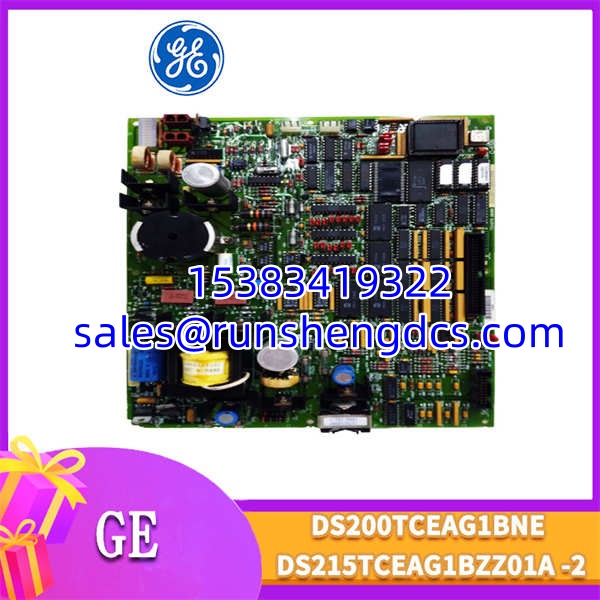
GE-DS200TCEAG1BNE-DS215TCEAG1BZZ01A
Functional Role & Application Analysis
The GE DS200TCEAG1BNE (and its equivalent DS215TCEAG1BZZ01A) is a critical safety-grade board within the Mark V turbine control architecture. Its primary role is to continuously monitor turbine shaft speed and flame status, acting as the ultimate fail-safe against catastrophic mechanical failure. When rotational speed exceeds predefined safe thresholds or flame is lost, this board immediately initiates a hard trip to shut down the drive.
The board achieves this through an onboard microprocessor and multiple Programmable Read-Only Memory (PROM) modules that store the safety logic. It relies on 30 configurable jumpers to adapt to specific turbine parameters and utilizes 3 internal fuses to protect its own monitoring circuits. The use of bayonet connectors ensures a secure, vibration-resistant mechanical lock to the backplane, which is vital in high-shake turbine environments.
Typical use cases include:
- Turbine Safety Trips: Acting as the primary or redundant overspeed protection layer in GE Frame 5, 6, 7, and 9 gas turbines.
- Flame Monitoring: Detecting combustor flame-out conditions to prevent unburned fuel accumulation and potential explosions.
- Preventative Maintenance: Replacing aging boards showing PROM degradation or jumper corrosion that cause nuisance trips.
- Legacy System Upgrades: Restoring safety integrity in older Mark V control cabinets during life-extension projects.
Our Quality Standard & Testing Process
We understand that the cost of an unreliable safety part is far greater than its purchase price. A failed overspeed board can lead to turbine destruction or an unwarranted plant blackout. We have established a rigorous, multi-stage testing process to ensure every DS200TCEAG1BNE we ship is 100% functional and calibrated.
Our professional QC process includes:
- Visual & Component Inspection: Thorough inspection of all 30 jumpers, 3 fuses, and bayonet connectors to ensure proper configuration, no physical damage, and zero corrosion.
- Live System Test: Installed in a live Mark V test rack for 24 hours to verify stable power draw, proper PROM reading, and continuous communication with the core processor.
- Full-Function Diagnostics: Simulated overspeed and flame-loss signals to verify the board correctly triggers the trip relay within milliseconds of the threshold being breached.
- Warranty Backing: Only parts that pass all diagnostic tests are approved for shipment and backed by our full 12-month warranty.
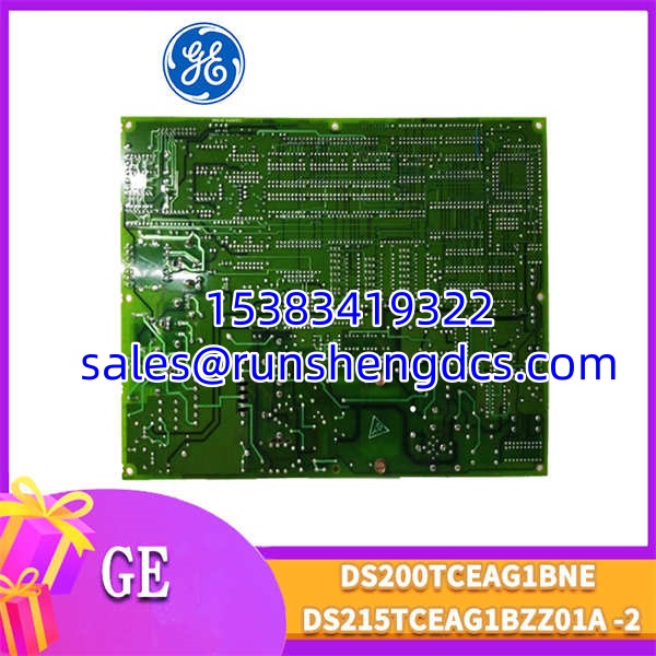
GE-DS200TCEAG1BNE-DS215TCEAG1BZZ01A
Compatibility & Migration Paths
To ensure this DS200TCEAG1BNE is 100% compatible with your system, you must check these key compatibility points. Failure to verify this is a common project risk that leads to safety system lockouts.
Key verification steps:
- Jumper Configuration Match: You MUST photograph and replicate the exact 30 jumper settings from your failed board. Incorrect jumper placement will cause the board to ignore overspeed signals or trip prematurely.
- PROM Module Verification: Confirm the part numbers on the PROM chips match your existing system. Mismatched firmware will prevent the board from passing Power-On Self-Test (POST).
- Bayonet Connector Seating: Ensure the bayonet connectors are fully aligned and locked. A loose connection under vibration will cause intermittent safety faults.
- Get Expert Help: Unsure about your board’s configuration? Contact our technical team today for a free compatibility check. Provide a photo of your existing board’s jumpers for exact cross-reference validation.